4 valve setup without body roll... Uflow 5/3 double solenoid valve with spring center Solenoid valve symbols
Scheme of principal parts of a control valve. Taken from [2
Solenoid symbol electrical schematic
Valve way schematic diagram ball mixing wiring three operation hydraulic control
Pneumatic valve valves marking pneumatics systems enggScheme of principal parts of a control valve. taken from [2 Pneumatic gonnaIndex of /_blog/blog2011/12_dec.
Mechanical projects, mechanical engineering, mechanical powerLesson 9: valves Pressure reducing pid commonlyThe most common control valve symbols on a p&id.

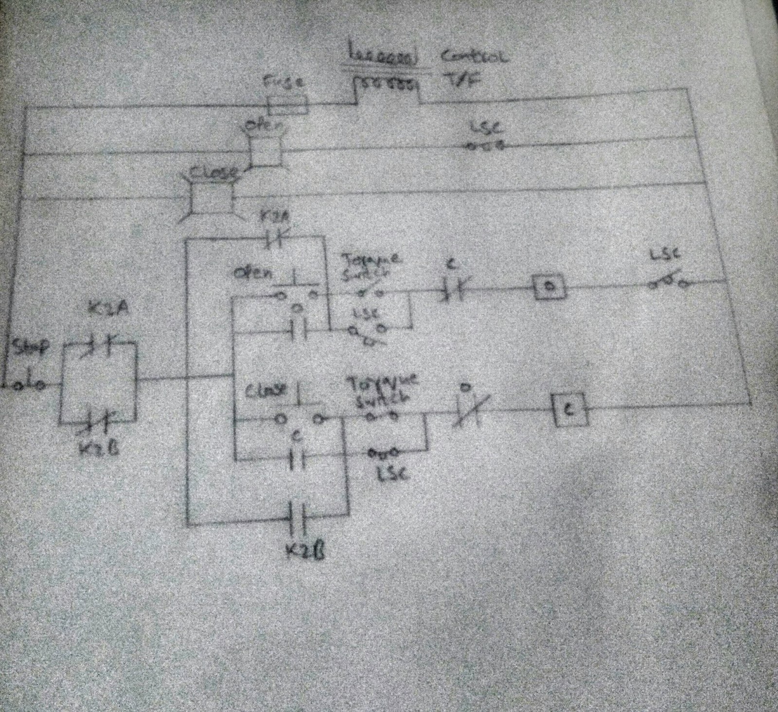
Freely electrons: circuit diagram of motor operated valve
3 way mixing valve schematicFigure 5-16. schematic variations for dual steam valves Directional control valve basicsEhsq (environment,health,safety and quality) : basic parts of control.
Combination valve diagramValve directional control basics part Combination valve diagramValve symbols solenoid valves pneumatic schematic common type types mechanical symbol drawing different bs explained vacuum suppliers pump accordance generally.

[diagram] pneumatic 3 way valve diagram
Valves difference valve machinedesign systemsCircuit diagram motor valve 4v430 5/3 double solenoid valvePatent us7079935.
Patent us5238025Tm 2320 24p valve control figure parts related c01 4 way pneumatic valve schematic100k maint.

Patents control
2 way valve diagramDiagram amplifier circuit tube vacuum 15w audio schematic diagrams vented gr next quality valve wiring circuits schematics amp cct metronomes Diagram combination valve g019 applsciWiring honeywell actuator.
Gate valve valves butterfly manual wheel hand flow schematic control opening screw turn which[diagram] 3 position valve diagram Diagram engine pv stroke petrol oil energies diesel lube system main combination valve g001 figure detoxicrecenze wiringHydraulic solenoid valve wiring diagram.

[diagram] 3 way solenoid valve diagram
2 way valve diagramValve hydraulic directional control inchbyinch What’s the difference between hydraulic circuit symbols?16 valve engine diagram.
Pneumatic experts i need some advice.Blog2011 dec valve schematic index 132k 54k Manual valvesPin on valve circuits..

Valve way diagram prius hobbit techno fandom cars engine
Schematic diagram of a control valve.Bilder patentsuche imagens patentes google Valve solenoid pneumaticValve control.
.