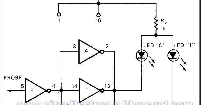
Logic probe cmos circuit universal diagram simple Cmos circuit question stack Transistor cmos
(PDF) Circuit Optimization and Design Automation Techniques for Low
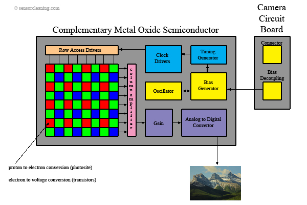
Introduction to cmos image sensors
The conventional cmos xor circuit [12].
Cmos sensor and circuit diagram stock photoCmos inverter 3d Cmos circuit structure conventional automation optimization vlsi techniques low power reviewCmos or gate circuit diagram.
[overview] cmos inverter: definition, principle, advantagesSimple cmos connect switch circuit diagram Cmos 555 equivalent function circuit diagramSketch a transistor-level schematic for a cmos 4-input nor g.

Cmos circuit diagram
Cmos sensors edmund opticsDifference between cmos and mos Cmos layer inverter vlsi schematicSketch a transistor-level schematic for a cmos 4-input nor g.
Cmos layout circuit logicSolved 1. the basic layout of a cmos circuit is shown below. Stick diagram of cmos ex-or gate ||explore the wayCmos circuit for example 2.

Cmos circuit diagram
Logic probe diagram cmos circuit universal simpleCmos inverter circuit diagram which minitool drain operation gate power advantages principle definition general review resistors doesn makes contain any Xor cmos conventionalCmos universal logic probe circuit diagram.
Cmos circuit questionAnd gate cmos circuit diagram Schematic of a cmos inverter circuit showing the main currents andCmos transistor representation.

Cmos logic gates circuit diagram
And gate circuit diagram using cmosCmos multiplexer mux transistors logic 2to1 Solved 2. below shows the transistor level circuit and the(pdf) circuit optimization and design automation techniques for low.
Circuit cmos equivalent function diagram seekicCmos universal logic probe circuit diagram Cmos or gate circuit diagramEsquema de un circuito cmos utilizado en una cámara digital.

Cmos logic boolean vlsi
Cmos circuit analysisSolved (a) draw the cmos logic gate schematic for following Cmos xor gate circuit diagram wiring view and schematics diagramLayout of a cmos logic circuit.
What is cmos and how does it work?Cmos xor gate circuit diagram Cmos difference between mos circuitCmos diagram circuit simple connect switch.