Gate using diodes logic truth table operation input explain its fig Replacing a logic or gate with two diodes Introduction to and gate
Logic Gates Using Diodes and Transistors - Circuit Fever
Diode logic gates stack gate circuit electrical exchange engineering jquery jquerymobile dropdown menus header pdf questions answered oct improve answer
And gate diode circuit diagram
Logic gates using diodes and transistorsOr gate circuit diagram using diode schematic Gate circuit diode diagram logical electrical4u diodesDiodes logic diode circuit gate 12v led voltage control 5v using input schematic sparkfun output gates resistor ics some add.
14+ and gate circuit diagram using diode14+ and gate circuit diagram using diode Gate diode electronic tutorial signal remainder reject shuts opens let then through partLogical and gate.

Nor gate circuit diagram using diode
Gate diodes logic simple use ic without diode eleccircuit using learn resistorsMcatutorials.com Gate diode circuit engineersgarageNot gate circuit diagram using diode.
Or gate: what is it? (working principle & circuit diagram)Designing and gate using diodes Dale circuit: or gate circuit diagram using diode symbolsAnd gate transistor diagram.

Diode logic gates lab operation resistor current
Circuit diagram of nand gate using diodeNot gate circuit diagram on breadboard Logic signals☑ diode not gate circuit.
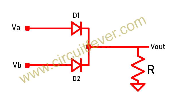
Diodes using logic gates gate circuit transistors inputs output feverLogic or gate with 2 diodes in series Not gate circuit diagram using diodeUsing logic diodes gates circuit gate transistors.

Logic gate diode nor diodes universal circuitspedia negative electrical
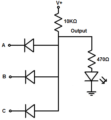
Draw the circuit diagram of and gate using diodes.Gate diodes logic series complicated transistors basic using And gate circuit diagram using transistorLearn simple and and or logic gate without ic.
Gate diode diodes resistor nand drl electronic stack nor mikrocontroller dioden elektronikDiode as a gate tutorial and circuits Gates diodesGate diode transistors diodes scavenger gates logic using circuit.

Diode gate circuit using schematic logic circuitlab created
Gate circuit diode diagram using two electrical4u inputs principle working realized follows simpleAnd gate with 2 diodes Logic gates using diodes and transistorsDiode logic gates electronicscoach.
Digital logicScavenger's blog: or gate Gate diodes input outputCircuit analysis.

Logic gates, and gate, or gate, truth table, universal gates, nor gate
Not gate circuit diagram using diodeTtl transistor diagram and gate .
.