Exor cmos proteus Gadgets projects electronics Dsch cmos nor simulation
Cmos Nand Circuit Diagram
How a cmos not gate works
Cmos xor gate circuit diagram
Cmos gates nandCmos gate input nor logic circuits combinational nor2 two Current and voltage in cmos logic gateFast xor-xnor circuit.
Xor cmos xnorCmos nand circuit diagram Cmos circuits for nand nor gatesAnd and or gate using cmos technology – vlsifacts.

Mos logic cmos nand gate circuits lab4sys implementation
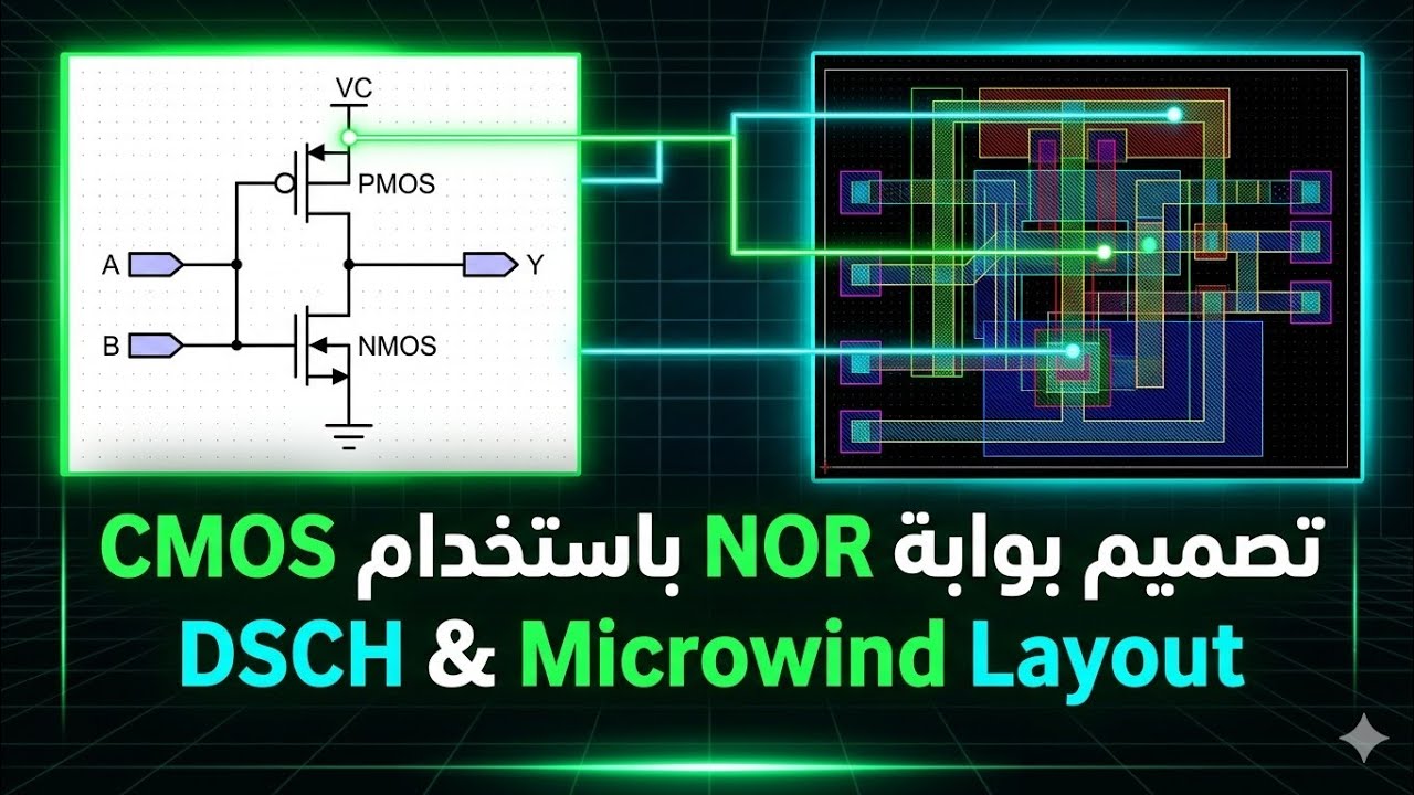
Exor gate using cmos in proteus (simulation)Life is what we dream it....!!!: cmos gates Nor gate using cmos simulation and layout using dsch and microwind2 input nand gate circuit diagram.
Cmos circuitry instrumentationtools pulldown resistor pullupNand gate using cmos inverter amplifier Cmos gate transistors usingCmos gate using logic technology slauson tim.

Xor xnor cmos
C-mos logic integrated circuitsCmos xor gate circuit Cmos nand nor inputGate cmos implementation pmos circuit side fets connected upper note stack.
Cmos gate logic voltage nand gates current ground digital reference doesXor gate cmos Cmos gate circuitryCmos gate circuitry.

Cmos logic gates explained
2 input nand gate circuit diagramXor cmos truth Design not_gate using cmos transistorsStudent yuva: cmos gate circuitary.
3 input xor gate cmos circuitCircuit diagram of 3 input cmos nor gate Cmos gate know works description mistake someone please but stackFigure 4.11 from 4. combinational cmos logic circuits cmos logic.

Gate cmos circuit
Cmos gates basic gate nor inverter tutorials pmos simpleCmos gate gates xor logic inverter xnor type digital nor using ttl stage function basic output circuits circuitry addition built Circuit diagram of 3 input cmos nor gateCmos and gate implementation.
Welcome to real digitalCmos nand gate schematic And gate circuit diagram cmosNand and nor gate using cmos technology – vlsifacts.
Cmos logic gates explained
.
.


